Sheet planning and material yield

Laser Cutting Sheet Sizes and Nesting Guide

Use the machine envelope, actual stock format, part orientation and process-specific clearance together. Supply controlled part files and production constraints; LCE prepares the final production nest against the confirmed sheet and cutting process.

Planning guidance reviewed 4 August 2026. Published dimensions are nominal working envelopes, not a guarantee that every material, sheet or geometry can use the full area.

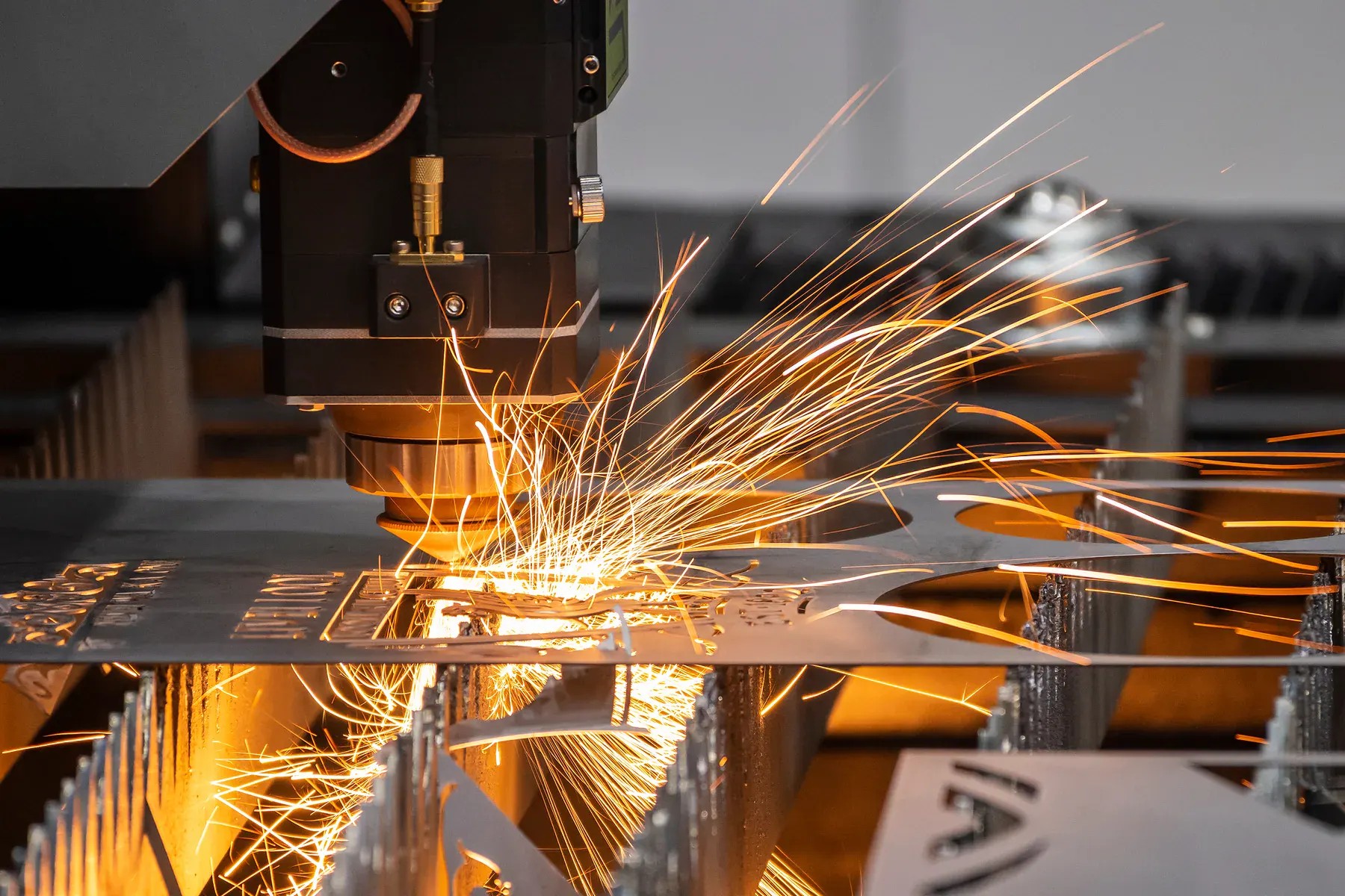
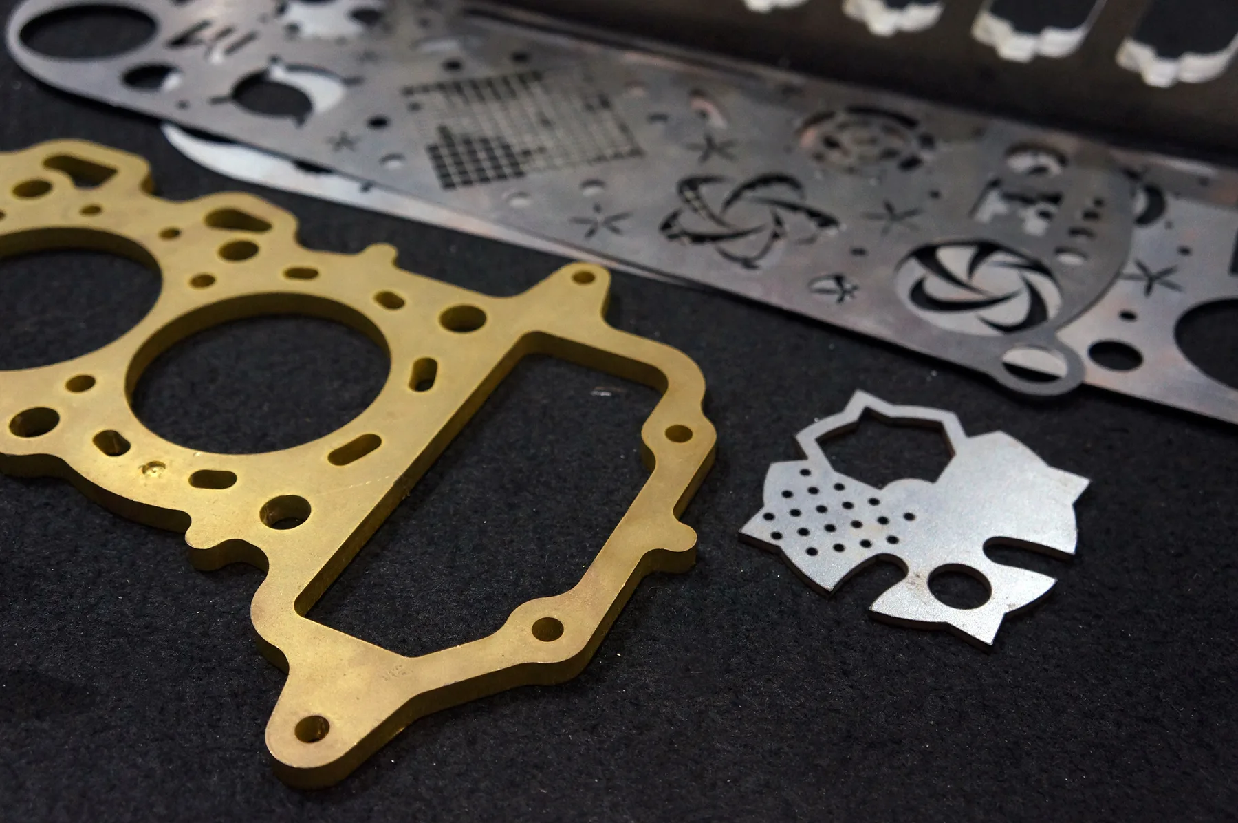
Fibre laser cutting nested sheet-metal profiles

Published LCE machine envelopes

These dimensions are useful for early planning. The usable nest can be smaller because of stock condition, edge quality, clamps, slats, vacuum hold-down, tool access, registration marks and the behaviour of the selected material.

ProcessPublished planning envelopeImportant qualification
Fibre laserUp to 3000 × 1500 mmFor suitable flat metal sheet and plate. Grade, thickness, surface condition and heat response affect the final layout.
CO₂ laserCore process page: up to 1200 × 900 mmThe acrylic route also documents a 3000 × 1500 mm large-format CO₂ table. Confirm which machine suits the actual material, thickness and finish.
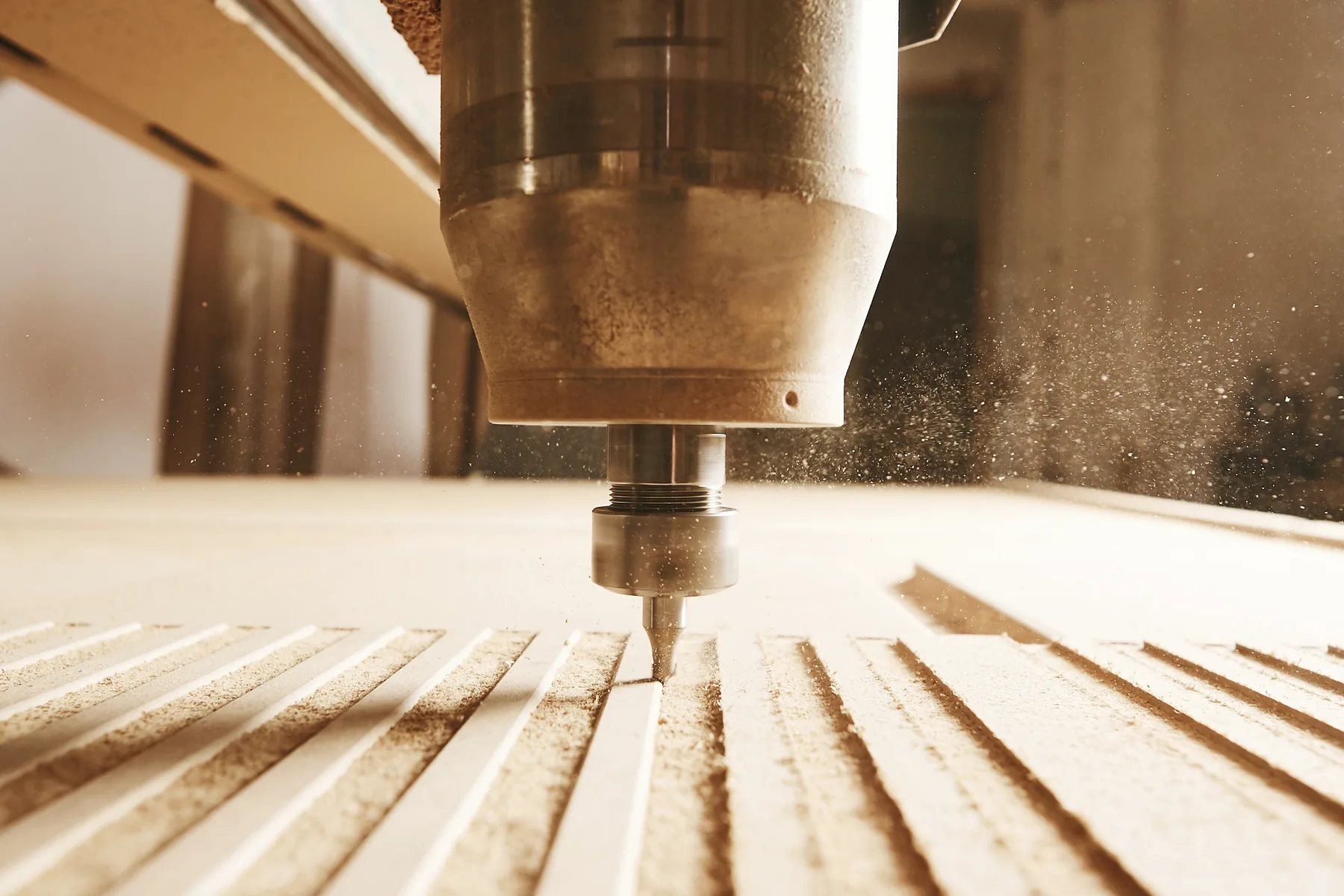
CNC routerUp to approximately 3000 × 1500 mmTool diameter, lead-ins, hold-down, clamps, tabs, pockets and edge condition can reduce the usable area.
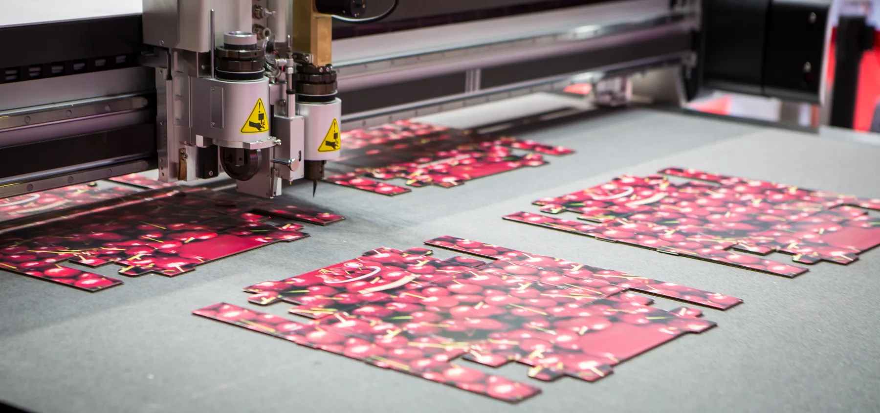
Digital knifeCore process page: up to 2500 × 1600 mmSome board routes publish handling up to 1500 × 3000 mm. Confirm the substrate, print registration and tool route before fixing a sheet map.

Four dimensions that must not be confused

A machine-bed number alone does not tell you how many parts fit or what the job will cost. Sheet planning uses four different boundaries.

1. Machine working envelope

The nominal area the machine can address. It is an upper planning limit, not automatic permission to place geometry against every edge.

2. Supplier stock format

The physical size available in the specified material, grade, thickness, colour and finish. It may be smaller than the machine bed, need trimming, or vary between suppliers and batches.

3. Usable nest area

The region that remains after the production team allows for sheet condition, edges, hold-down, registration, clamping, lead-ins and the selected cutting strategy.

4. Part bounding box

The smallest rectangle that contains the finished profile at its approved orientation. Rotating a part can improve yield, but rotation may be restricted by grain, brushed finish, flute, print or functional direction.

Stock-size examples, not stock promises

Current LCE material pages cite common examples including 2440 × 1220 mm and 2400 × 1200 mm for selected boards, and 1220 × 2440 mm or 1500 × 2000 mm for selected acrylic sheet.

Availability changes with material, grade, thickness, colour, finish and supplier. Confirm the actual sheet before using a format to calculate quantities, joins or installation details.

Why there is no universal spacing or edge-margin rule

A fixed gap copied across every material and process can cause poor hold-down, heat distortion, tool collisions, damaged edges or unnecessary waste. Final spacing is a production decision based on the real job.

Fibre laser

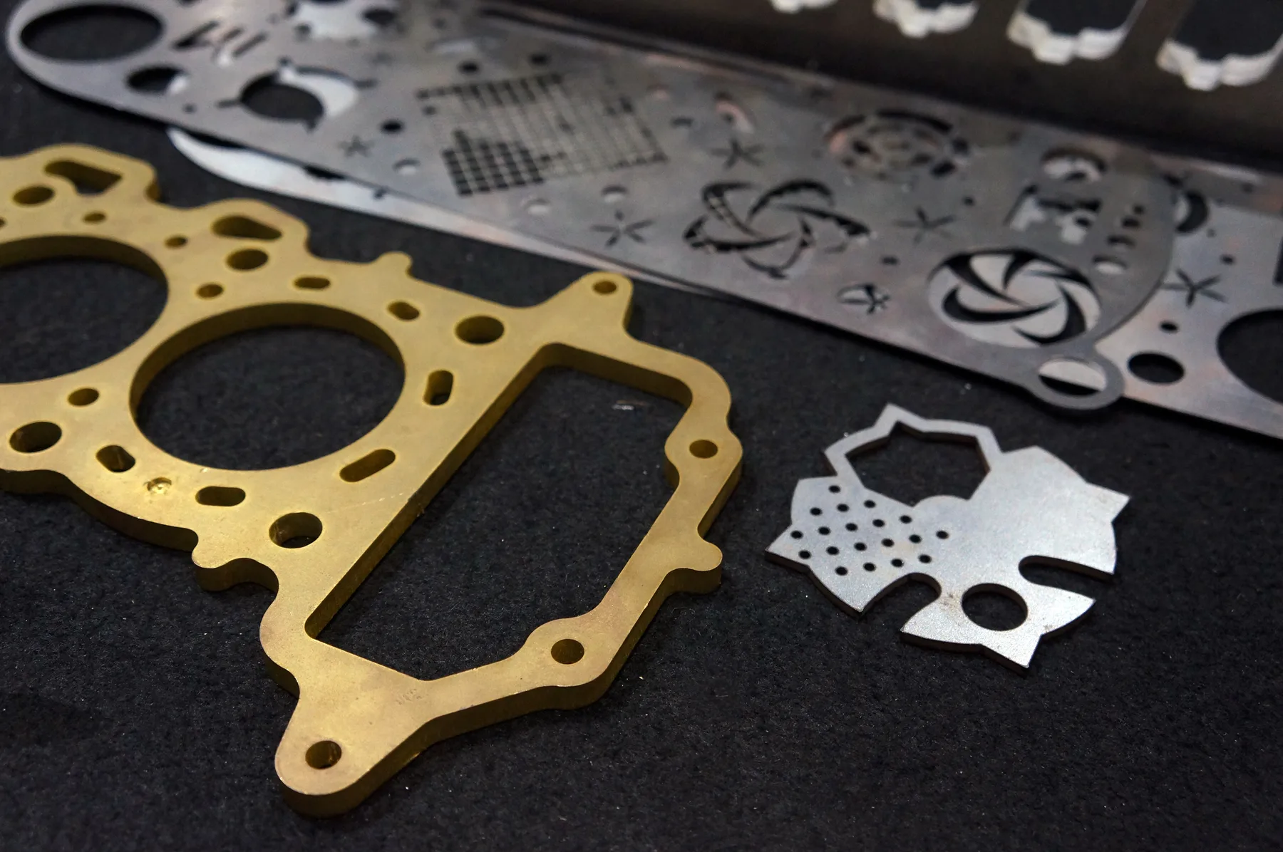
Kerf, piercing, thermal concentration, material thickness, skeleton stability, slat condition and the order of cuts affect safe part spacing and edge allowance. LCE applies the cutting compensation and final metal-sheet nest.

CO₂ laser

Material type, thickness, kerf, heat sensitivity, protective film, small-feature stability and edge-finish expectations influence the layout. Acrylic, timber and other approved materials do not share one universal rule.

CNC router

Tool diameter, lead-in and lead-out paths, pockets, rebates, tabs, vacuum zones, clamps, chip clearance and the remaining sheet skeleton all affect how closely parts can be placed.

Digital knife

Blade path, material compression, flute or grain direction, vacuum hold-down, print registration, cut and crease operations and sheet flatness determine the practical margin and clearance.

What the customer should define

The production file should describe the approved finished part, not an assumed full-sheet arrangement. Provide the constraints that must survive nesting.

  • One approved profile per controlled part file where practical
  • Part number, drawing number and current revision
  • Material, grade, thickness, colour and finish
  • Required quantity for each part or kit
  • Grain, brush, flute, film, print or face direction
  • Critical dimensions, fit features and orientation restrictions
  • Grouping, matched-set, labelling and packing requirements
  • Any customer-supplied sheet or remnant dimensions and condition

What LCE controls in the final production nest

The production team places approved geometry against the sheet and process that will actually be used. That work can include:

  • Confirming the real stock size and usable sheet area
  • Applying kerf, blade-path or tool-path compensation
  • Setting process-appropriate part spacing and edge allowance
  • Rotating parts where the specification allows it
  • Managing heat, hold-down, skeleton stability and cut sequence
  • Combining approved parts where material and scheduling permit
  • Assessing common-line strategies only where technically suitable
  • Calculating sheet usage for the reviewed quotation and production plan

File preparation before nesting

Clean geometry makes reliable sheet planning possible. Use the existing DXF guide for file preparation, then keep the nesting brief separate from the part definition.

  • Draw at 1:1 scale in millimetres unless another unit is clearly agreed
  • Use closed vector paths with no duplicated, overlapping or stray geometry
  • Keep the approved part close to the drawing origin
  • Identify separate operations such as profile, pocket, engrave, crease or perforation
  • Do not add manual kerf offsets to the nominal finished geometry unless specifically requested
  • For a multi-part file, keep outlines visibly separate and state whether their relationship is functionally fixed

Do not force a full-sheet layout by default

A customer-created sheet map may use an unavailable stock format, ignore process clearance or block a more efficient production arrangement.

Submit clean part geometry and the required quantities. If a fixed layout is genuinely required, mark it clearly and have it reviewed before it becomes the approved production reference.

When a customer-supplied sheet map can be appropriate

Some projects have constraints that only the customer or designer can define. In those cases, supply the layout as a controlled requirement and explain why it must be preserved.

Printed sheets

Artwork position, bleed, registration marks and sheet orientation control where the cut can be placed.

Directional finishes

Brushed metal, timber grain, flute, film, fabric direction or visible face may prevent free rotation.

Matched sets

Sequenced panels, repeated patterns or adjacent visual components may need a controlled sheet relationship.

Supplied remnants

Provide measured dimensions, material identity, thickness, flatness, edge condition and any surface damage for review.

Fixed kit grouping

Parts may need to remain grouped for batch identity, traceability, print matching or downstream packing.

Approved sheet map

A previously reviewed map can be retained when the file revision, stock, process and all production assumptions remain valid.

Yield and quotation

Sheet yield influences material cost, but a simple area calculation is not enough. Two parts with the same area can nest very differently because of shape, orientation, internal waste and process clearance.

The reviewed quotation can account for material, thickness, actual sheet usage, cut length, pierces, tool or operation changes, nesting yield, quantity, handling, finishing and delivery. Use that result rather than treating a drawing-screen count as the final commercial yield.

Offcuts and remnants

A leftover shape is not automatically suitable for another job. Material identity, grade, thickness, batch, finish, protective film, rust or damage, edge condition and traceability all affect whether it can be used.

If supplied stock, remnant return or a future reuse plan matters, include it in the quotation request. Do not assume storage, ownership, return or reuse unless the written scope confirms it.

Sheet-size and nesting FAQs

Usually, send clean approved part geometry with quantities, material and orientation constraints. LCE prepares the production nest against the actual stock and process. Supply a fixed sheet map only when print, grain, matching, supplied stock or another controlled requirement makes it necessary.

There is no universal gap. Material, thickness, kerf, heat, piercing, feature geometry, sheet stability, cut sequence and the selected process affect safe spacing. Define the finished part and let LCE apply production clearance unless a specific layout has been reviewed.

No. The published bed is a nominal planning envelope. Actual stock size, edge condition, hold-down, clamps, slats, registration, tool access and process requirements can reduce the usable nest area. Confirm the real job before committing a design to the maximum dimensions.

Yes, where the approved specification permits rotation. State any grain, brush, flute, print, film, face, structural or assembly direction that must be maintained. Unmarked directional requirements cannot be protected reliably during nesting.

Suitable customer-supplied stock can be reviewed. Provide the material identity, grade, thickness, exact dimensions, finish, flatness and condition. Acceptance, handling, risk, usable area and any return arrangement must be confirmed in the written quotation.

Need the right sheet and nest for your parts?

Send the approved files, material specification, quantities, orientation constraints and required date for a reviewed production plan.

Cutting Engineering & Fabrication in Sydney. Laser Cutting Experts Offers High-Precision Cutting Services for Engineering & Fabrication in Sydney Australia.