Flat equipment and enclosure components

Laser Cut Panels, Covers and Enclosure Plates

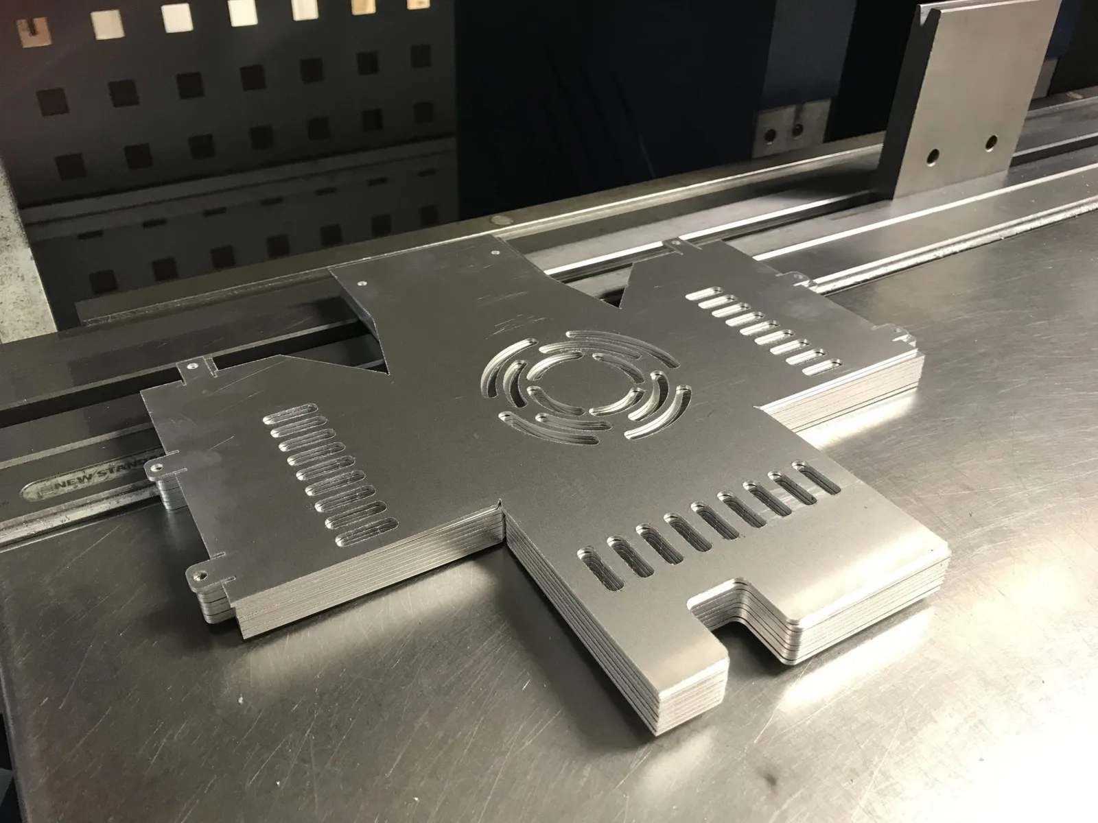
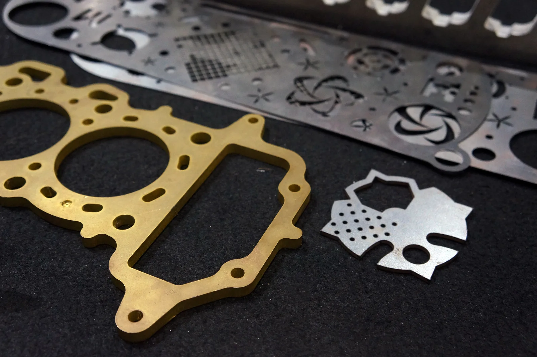
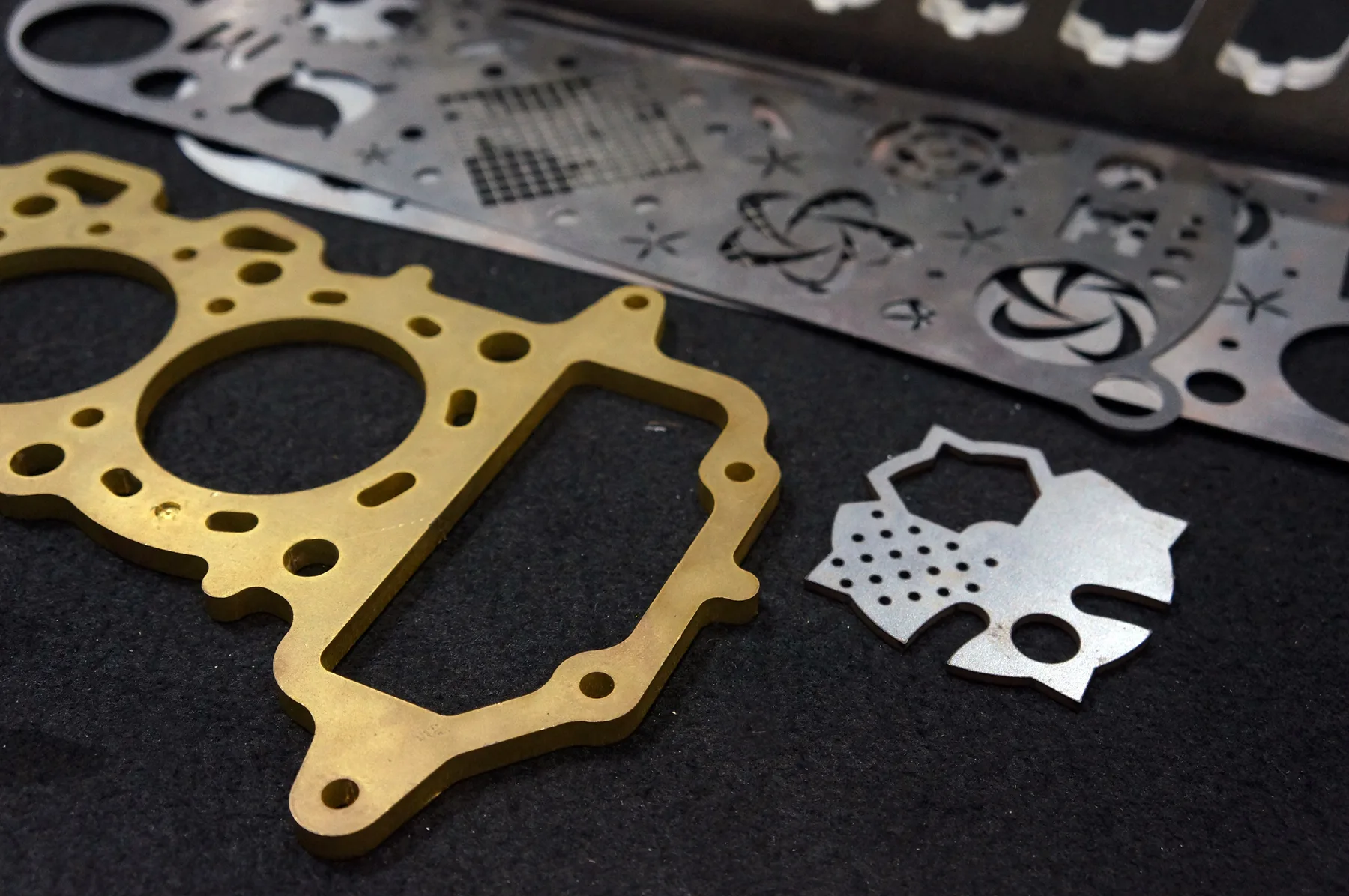
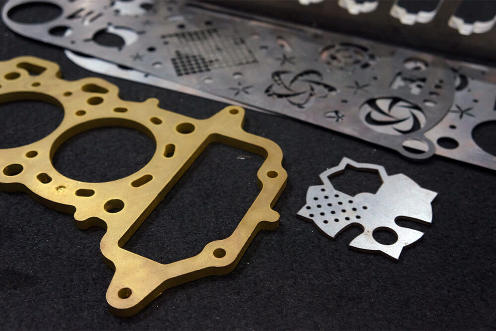
Flat metal panels, faceplates, covers, blanking plates and equipment plates cut from approved CAD files with the holes, slots, apertures and mounting features already defined.

LCE supplies flat cut parts unless a written quotation expressly includes another operation. Enclosure design, folding, assembly, wiring, ratings and final compliance remain outside the cutting scope.

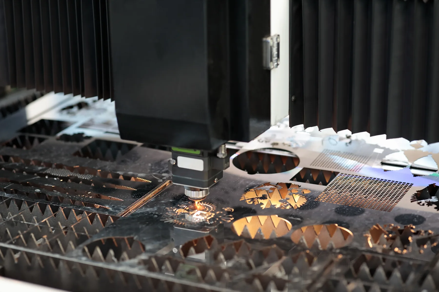
Nested stainless steel equipment panels cut from sheet

Panel and cover components within this service

This page is for defined flat components that close, face, mount to or provide access to equipment and fabricated assemblies. It is not a substitute for the engineer, fabricator or electrical specialist responsible for the complete enclosure.

Faceplates and fascias

Flat fronts for controls, displays, indicators, switches and equipment interfaces, with approved apertures and mounting features included in the cut file.

Covers and blanking plates

Removable flat covers, closure plates and blanking panels used over defined openings in machinery, cabinets, frames and fabricated assemblies.

Access and service panels

Panels with holes, slots, handles, fastener positions or inspection openings defined by the party responsible for access and maintenance design.

Mounting and backing plates

Internal equipment plates, terminal or component mounting plates and flat back panels prepared for the customer’s later hardware and assembly workflow.

Machine and equipment panels

Flat side, top or interface panels where the approved drawing controls profile, openings, service clearances and fastener locations.

Panel sets and revisions

Related panels can be identified by part number, revision, equipment reference and quantity for controlled production and later reordering.

Flat panel cutting versus a finished enclosure

LCE’s standard deliverable is the flat component shown in the approved cutting file. The design may later become part of a folded, welded, sealed, wired or assembled product, but those outcomes cannot be inferred from the cut profile alone.

For a future folded panel, the customer or nominated fabricator supplies and approves the developed flat pattern, including bend reliefs and geometry needed for their tooling. LCE does not derive a production flat pattern from an unapproved finished-box concept as part of ordinary profile cutting.

Selected laser welding or finishing can be reviewed separately where the relevant service is available, but it is included only when the written quotation states the operation, material, acceptance criteria and owner. A reference to a cover or enclosure plate does not mean a complete enclosure is being supplied.

Ratings remain with the complete assembly

A correctly cut plate does not establish an IP, NEMA, electrical, thermal, structural, pressure, fire, hygienic or safety rating.

Seal design, gasket compression, hardware, hinges, fasteners, cable entries, ventilation, earthing, material selection, fabrication, installation and testing must be approved by the responsible designer, fabricator or qualified specialist.

Material and cutting route

Select the material from the project specification, not from appearance alone. The required strength, corrosion resistance, weight, finish, downstream fabrication and operating environment determine which route should be reviewed.

Mild steel

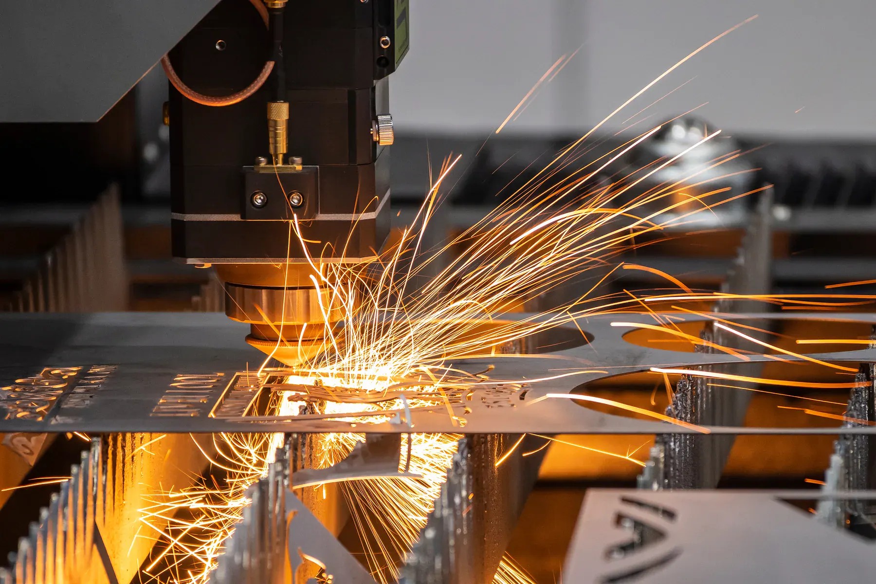
Suitable for approved equipment panels, covers, guards and mounting plates where the design allows carbon steel. The current mild-steel route publishes fibre-laser capability up to around 15 mm depending on grade and job requirements.

Parts are supplied flat and can be prepared for the customer’s nominated welding, priming, galvanising, painting or powder-coating workflow.

Stainless steel

Current LCE material guidance specifically includes stainless covers, faceplates and control-panel fascias. State the required stainless type, thickness and visible finish rather than treating every stainless sheet as interchangeable.

Direction-sensitive brushed finishes and protective film must be identified before nesting and cutting.

Aluminium

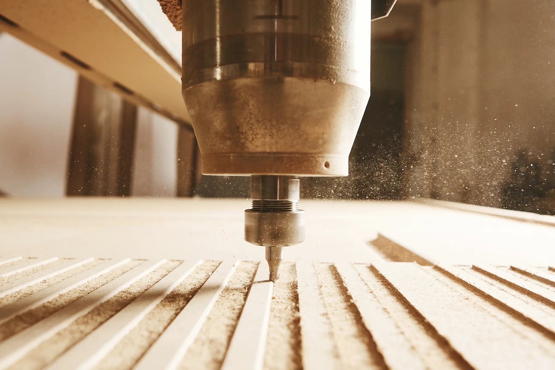
Current aluminium guidance includes mounting plates, heatsink plates and control-panel fascias. Fibre laser suits approved profile cutting, while CNC routing can support selected countersinks, pockets, engraving and V-grooving.

State the exact alloy, temper, thickness, face and finish required by the design.

Approved non-metal panels

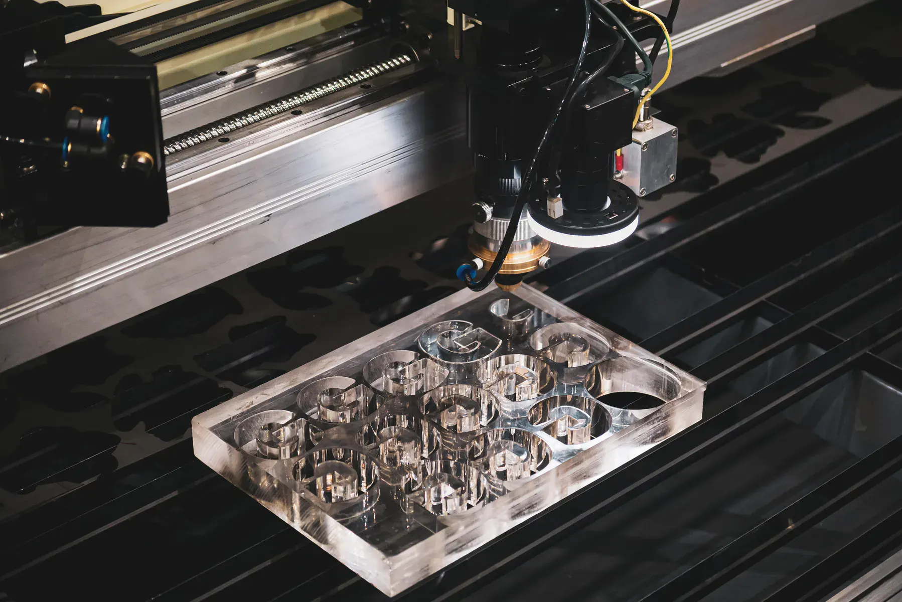
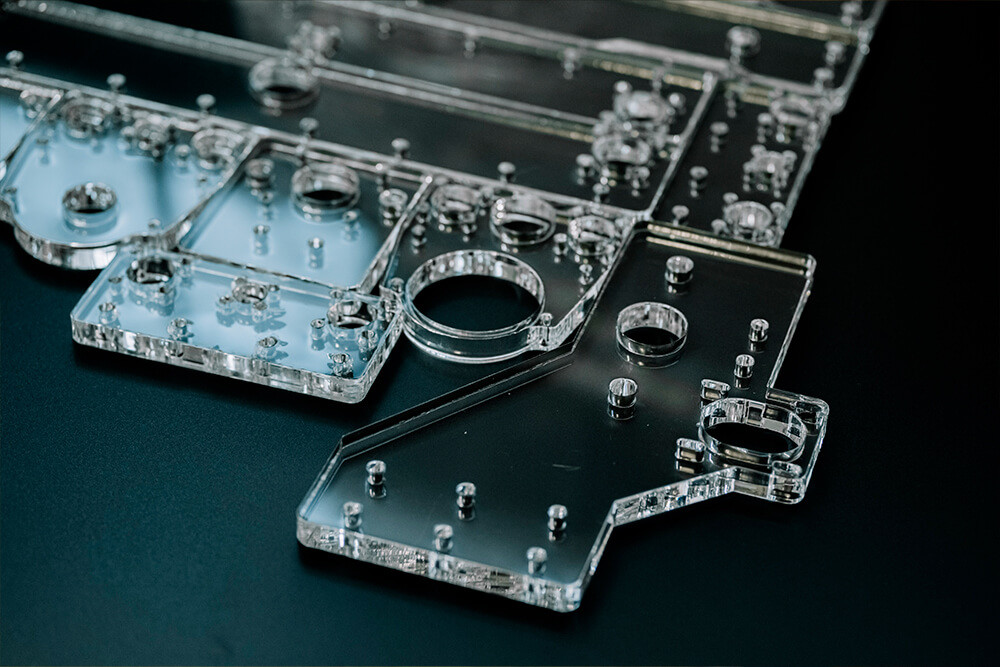
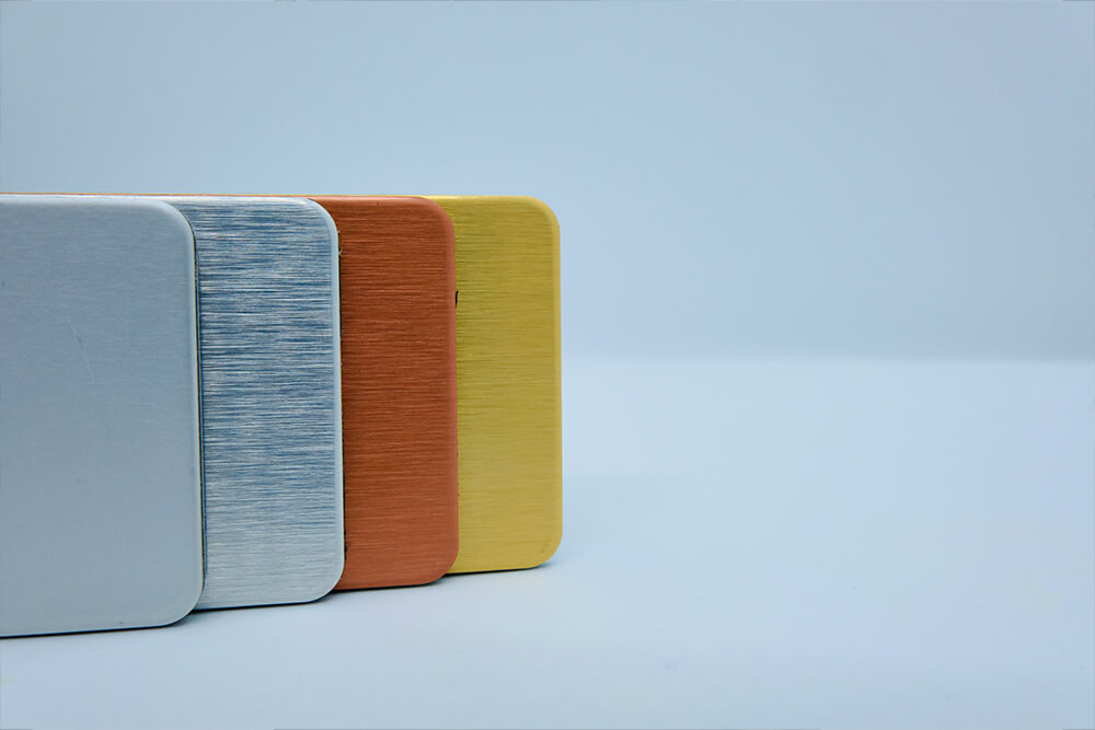
Acrylic, polycarbonate, engineering plastics, ACM and other sheet products use a material-appropriate CO₂ laser, CNC router or digital process rather than being sent automatically to the metal laser.

The material page and reviewed quotation determine the safe process, sheet envelope, finish and flat-part boundary.

Profile features prepared from CAD

A controlled 2D file can define the finished perimeter and every feature that should be produced in the same cutting setup.

  • Outer profiles and corner geometry
  • Circular, slotted and shaped mounting holes
  • Switch, display, fan, connector and cable apertures
  • Ventilation patterns and approved perforation arrays
  • Tabs, keys, locating features and assembly slots
  • Handles, inspection openings and service cut-outs
  • Part marking or engraving layers where the selected process permits them

Features requiring reviewed production

Not every feature is a simple through-cut. Identify the required face, hardware and final dimensions so the correct process and commercial route can be confirmed.

  • Countersinks, counterbores, rebates and pockets
  • Engraving, labels and part identification
  • Very fine ventilation, narrow webs or dense hole fields
  • Features close to an edge or another aperture
  • Visible faces with directional grain or protective film
  • Customer-supplied, printed or pre-finished sheet
  • Parts needing selected welding, painting or other separately quoted work

Drawing information that prevents panel errors

Fit problems usually come from an incorrect or incomplete interface definition rather than the cutting path alone. Release the panel file only after it has been checked against the mating equipment and real hardware.

  • Supply DXF or DWG at 1:1 scale in millimetres; suitable vector PDF, AI, EPS or SVG can also be reviewed
  • Use closed paths with no duplicate, overlapping or stray geometry
  • Identify the part number, drawing number and current revision
  • State material, grade, thickness, finish, face side and quantity
  • Mark critical dimensions and the mating or hardware references used to approve them
  • For countersinks, identify the required face, finished diameter, angle or hardware standard and depth requirement
  • Separate cut, pocket, engrave and other operations by named layer or clear instruction
  • Use a STEP file as assembly context where useful, but identify the approved 2D profile that controls cutting

Do not compensate the CAD profile twice

Supply nominal finished geometry unless LCE specifically asks for another convention. The production team applies the relevant kerf or tool-path compensation during programming.

If a slot, hole or opening has a functional fit, mark the required finished result and tolerance. Do not silently enlarge or shrink geometry to account for an assumed process.

Controlled production workflow

A clear release path keeps the correct panel revision, material and secondary operations together.

1

Define the component

Confirm the panel’s finished profile, material, thickness, face, quantity, critical interfaces and downstream owner.

2

Release the file

Issue the approved 2D drawing with a stable part number and revision. Identify any STEP reference and superseded files.

3

Review the process

LCE confirms the material route, sheet planning, cutting method, reviewed operations and the information required to quote.

4

Approve the scope

Check the written quotation against the file revision, quantities, included operations, finish, packing and required dispatch date.

5

Cut and identify

Parts are produced from the controlled file and can be grouped or labelled by part, panel set or equipment reference when quoted.

6

Inspect the downstream fit

The responsible team verifies fit, assembly, sealing, electrical and functional requirements before the panel is released into its final use.

Pricing inputs

Panel pricing is driven by material and thickness, sheet usage, cut length, pierce count, feature density, nesting, quantity, handling and any reviewed CNC or finishing operation.

Clean cutting-only files with a known material, thickness and quantity can use online pricing. Use a reviewed quotation for countersinks, pockets, engraving, visible finishes, supplied sheet, many part numbers, coordinated sets or another operation outside straightforward profile cutting.

Scheduling and repeat production

Current core cutting pages publish typical dispatch guidance of 1–5 business days after the applicable drawing or artwork is approved and material is confirmed. The written quotation controls the job-specific date.

For recurring panels, keep the approved master file, part number, revision, material, finish and equipment reference under customer control. A previous job reference helps identify history, but the current approved revision must remain unambiguous.

Panels, covers and enclosure-plate FAQs

No. The standard scope is flat cut panels, plates and covers. Folding, full fabrication, assembly, wiring, hardware, sealing and certification are handled by the customer’s nominated specialists unless a written quotation expressly states a selected additional operation.

Yes. Include every approved feature as controlled vector geometry and mark any critical fit or position. The customer or responsible designer must verify the drawing against the real hardware, equipment and assembly before release.

Selected panels can be reviewed for CNC-routed countersinks, pockets, rebates or engraving. Identify the operation, required face, finished dimensions and hardware or marking specification. These operations require a reviewed quotation rather than being assumed from the profile file.

No. Ratings apply to a designed, assembled and tested system, not automatically to a flat cut component. The responsible specialist must control sealing, gaskets, hardware, entries, ventilation, earthing, fabrication, installation, testing and compliance.

DXF or DWG at 1:1 scale is preferred. Suitable vector PDF, AI, EPS or SVG can also be reviewed. Include the material, thickness, quantity, part number, revision, critical dimensions, finish face and clearly separated instructions for any operation beyond through-cutting.

Ready to quote controlled panel and cover files?

Send the approved drawings, material, thickness, quantities, face and finish requirements, included operations and required date.

Cutting Engineering & Fabrication in Sydney. Laser Cutting Experts Offers High-Precision Cutting Services for Engineering & Fabrication in Sydney Australia.