Fit-up parts
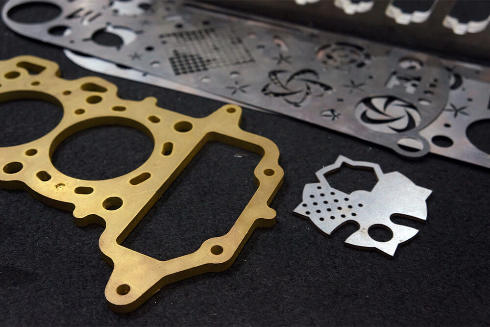
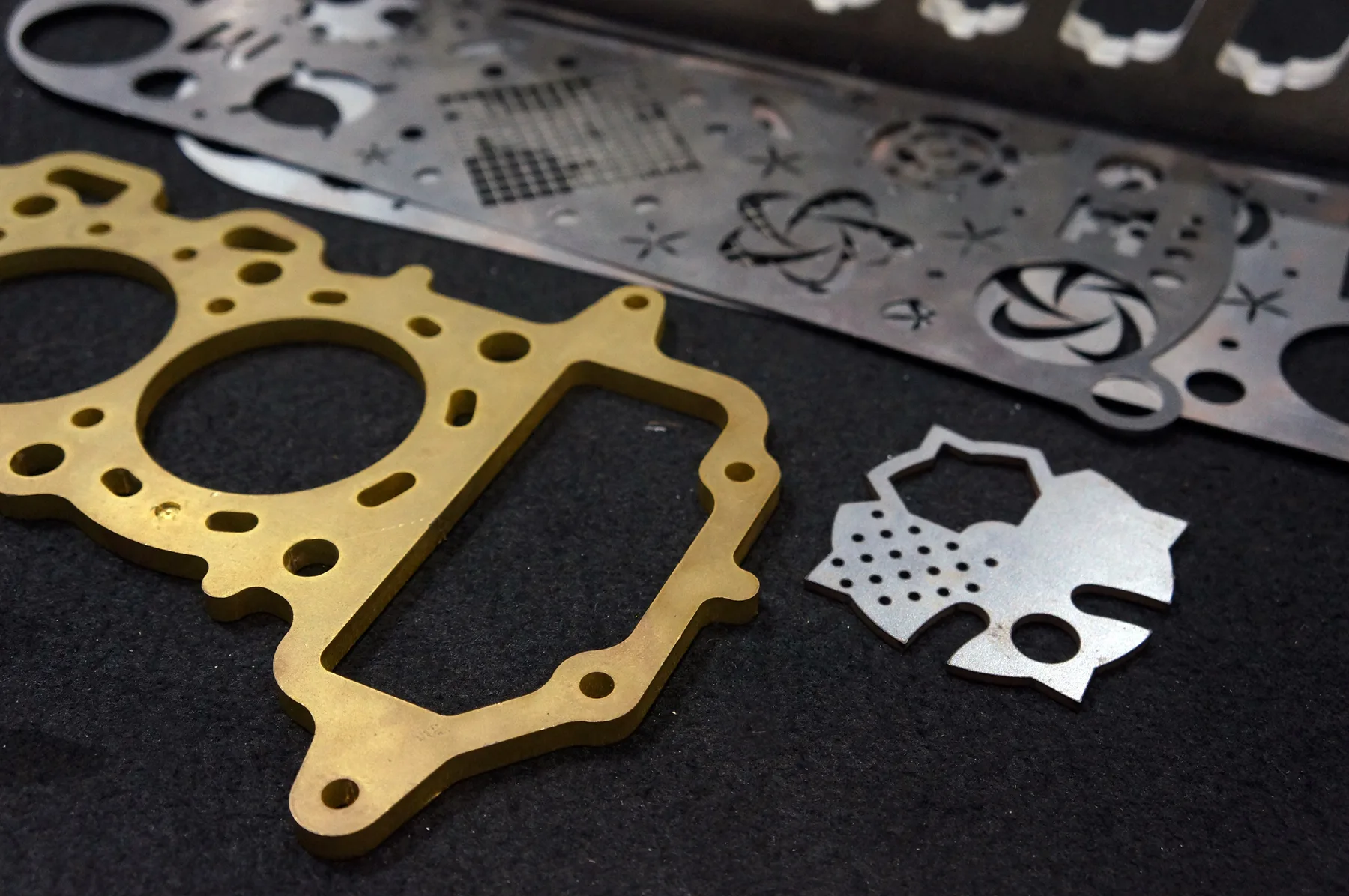
Slots, tabs, brackets and spacers where material thickness, kerf and hole size influence assembly.

Tolerances
A practical tolerance guide for buyers who need parts to fit, align, repeat or assemble correctly without treating every material and process as identical.
What we cut
A practical tolerance guide for buyers who need parts to fit, align, repeat or assemble correctly without treating every material and process as identical.
Start with the part, panel or material you need. Use fast online pricing when the file is cut-ready, or request review when the job needs production input before it can be accepted.
Slots, tabs, brackets and spacers where material thickness, kerf and hole size influence assembly.
Files that must produce the same result across future runs and revisions.
Acrylic, metal and ACM panels where face quality and edge presentation matter.
Holes and slots that need to align with fixings, hardware, frames or existing parts.
Old parts copied from samples, photos or measurements should be reviewed before production.
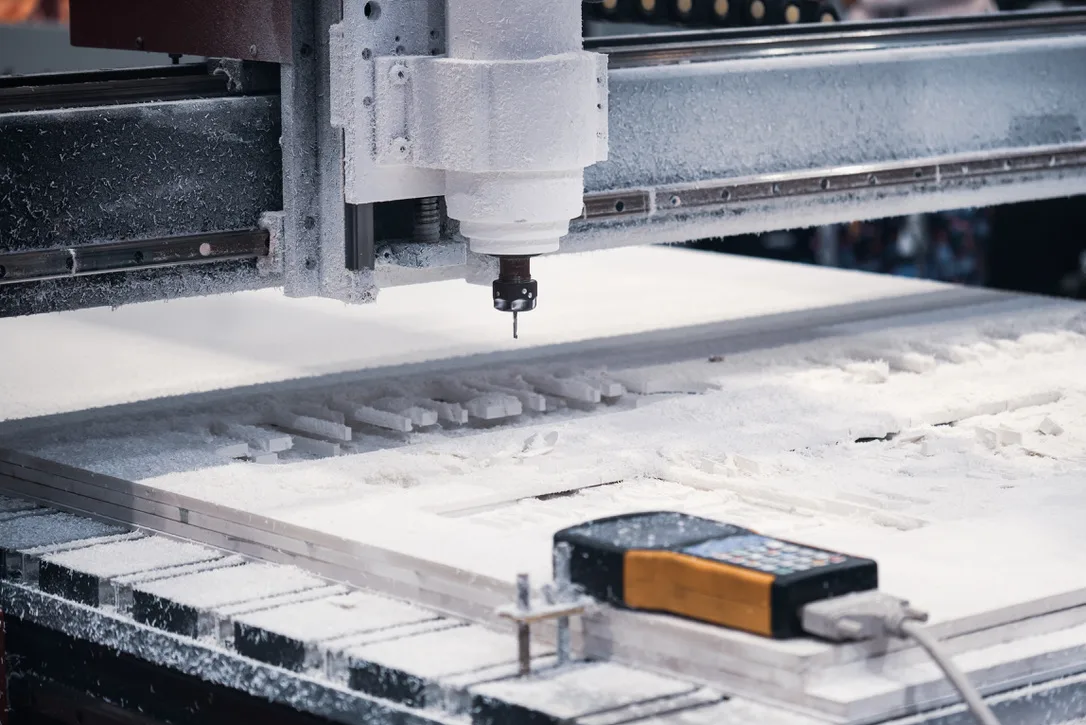
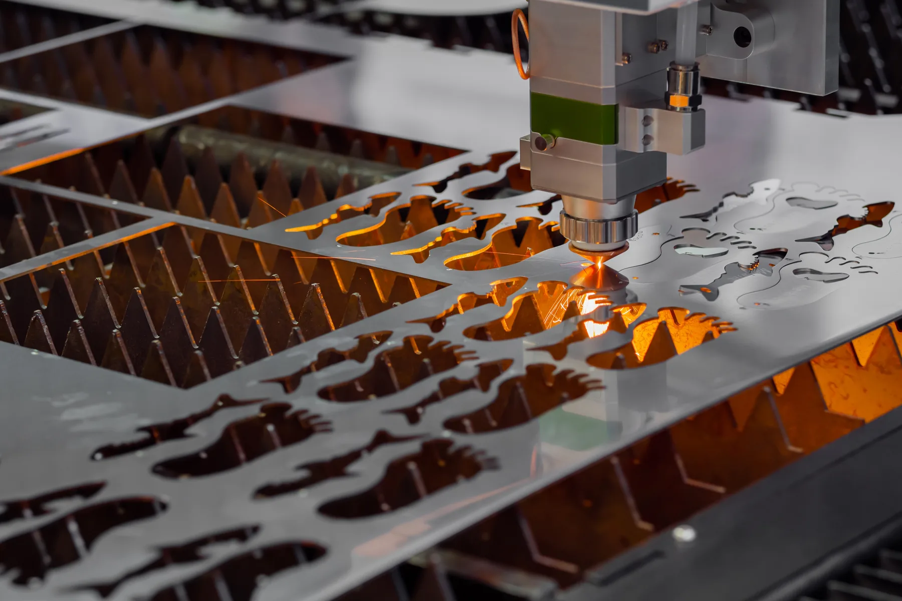
Laser, router and knife cutting each behave differently, so process selection affects tolerance expectations.
Project gallery
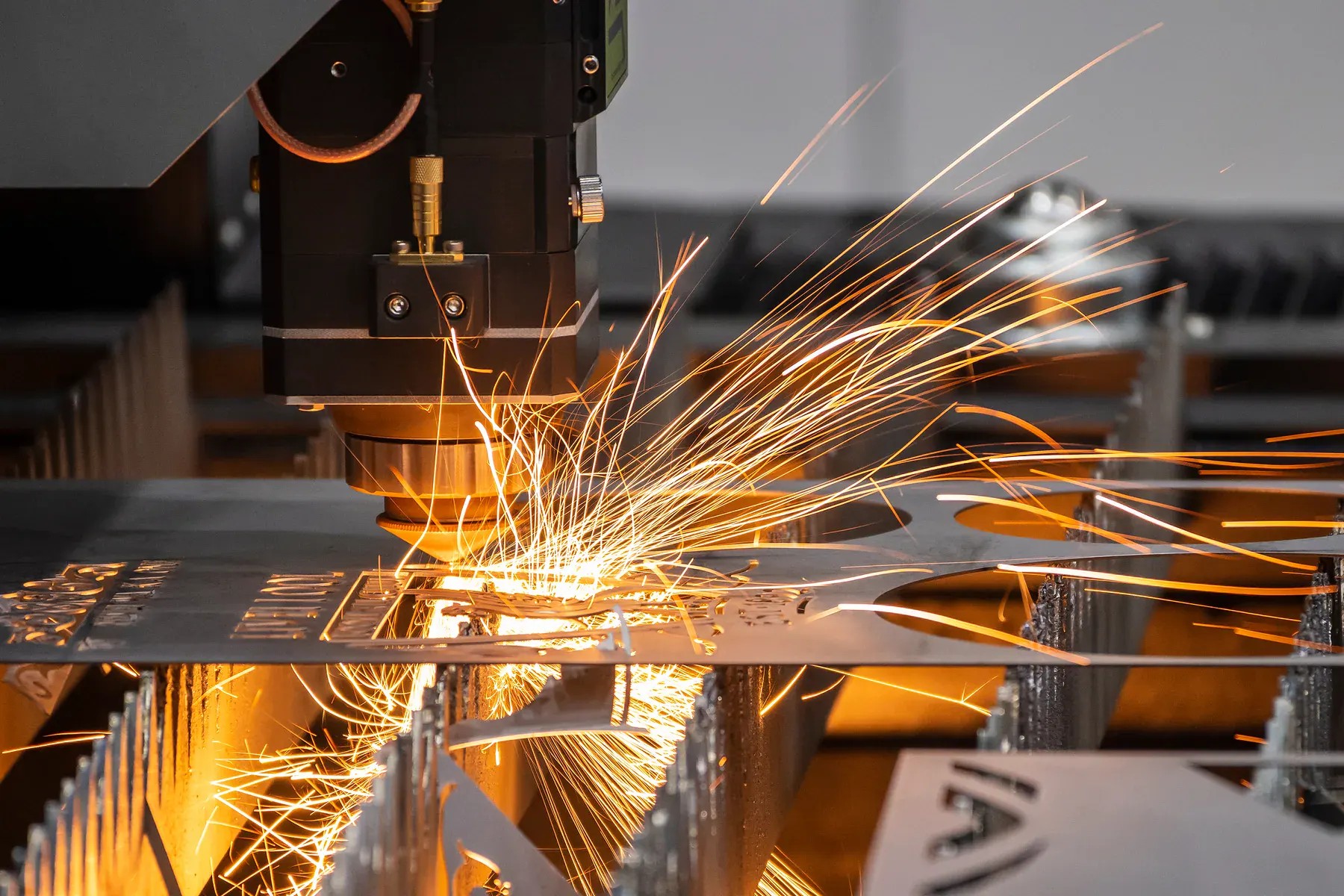
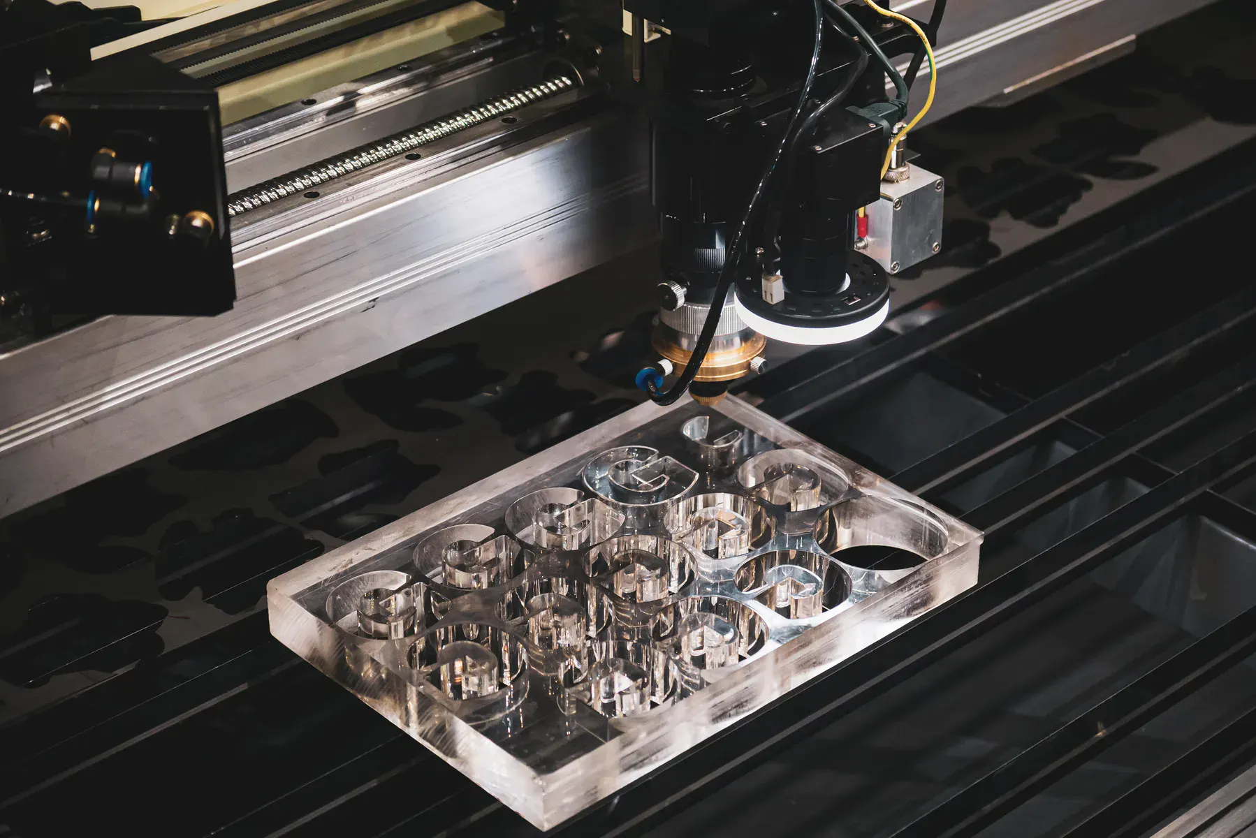
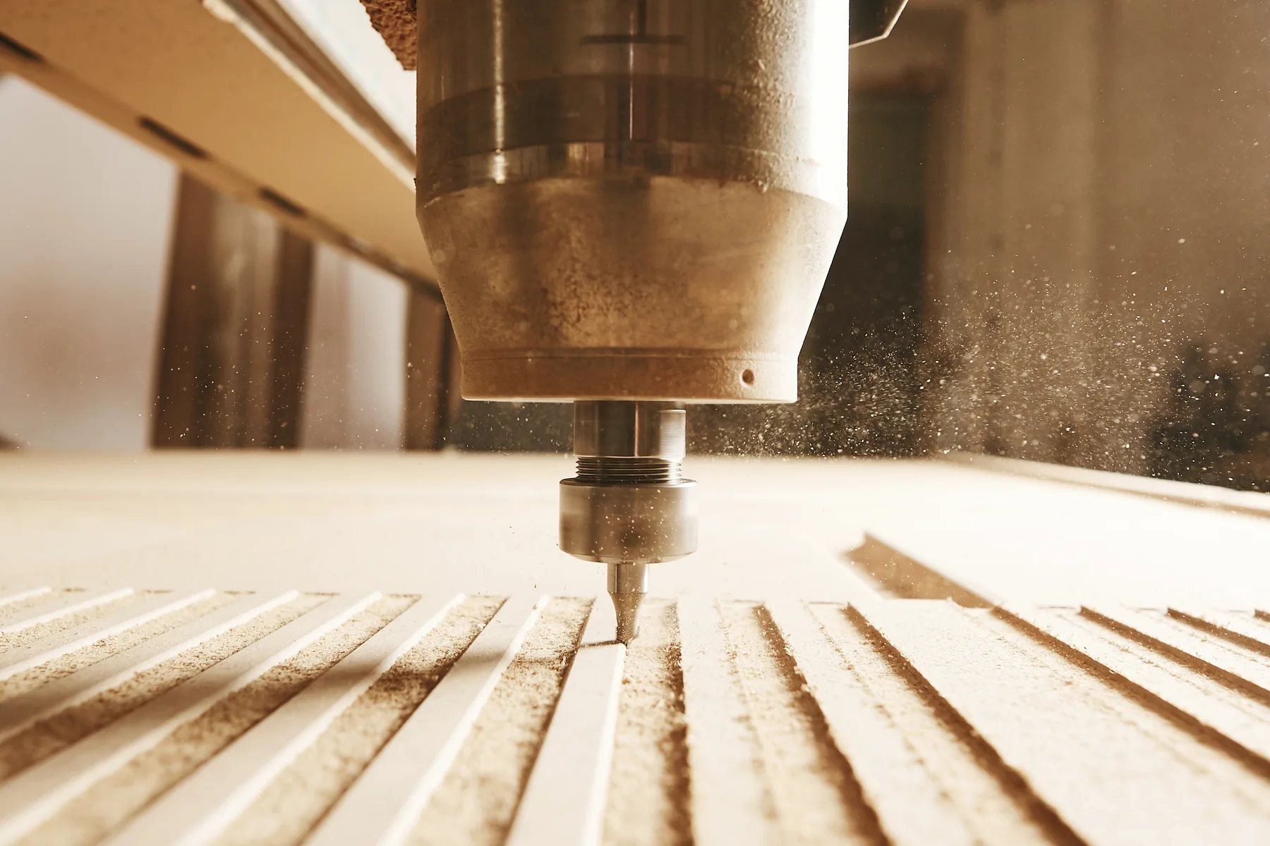
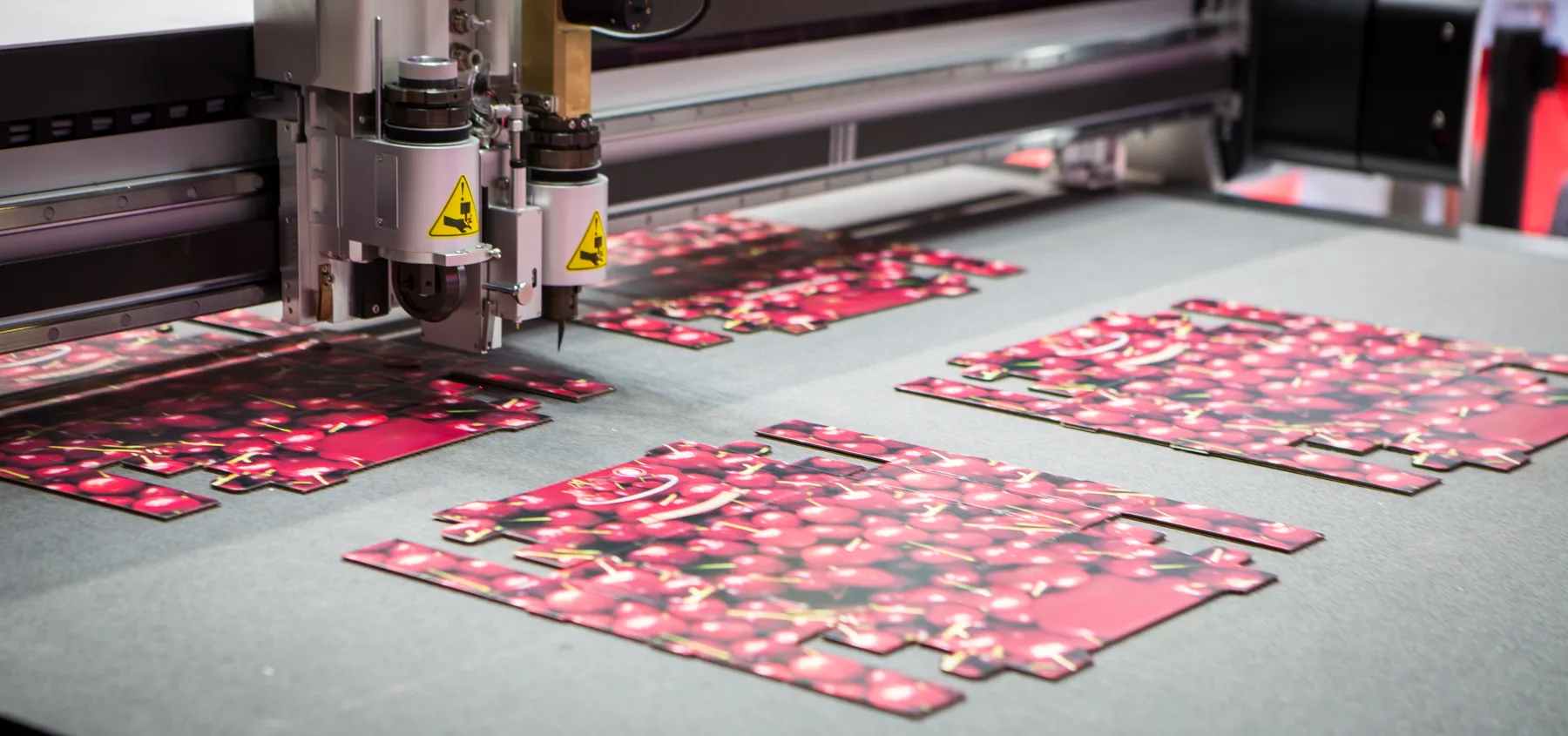
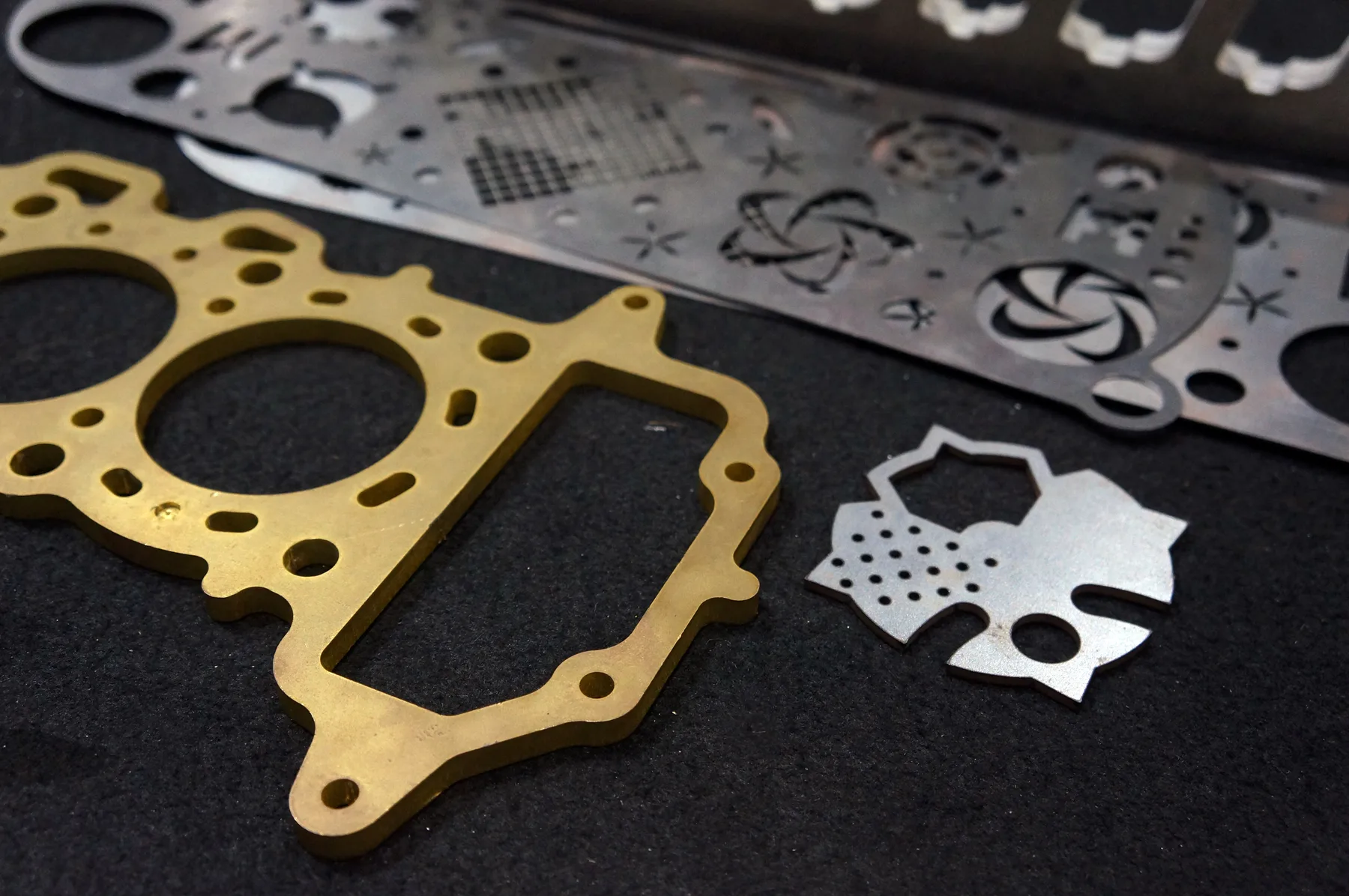
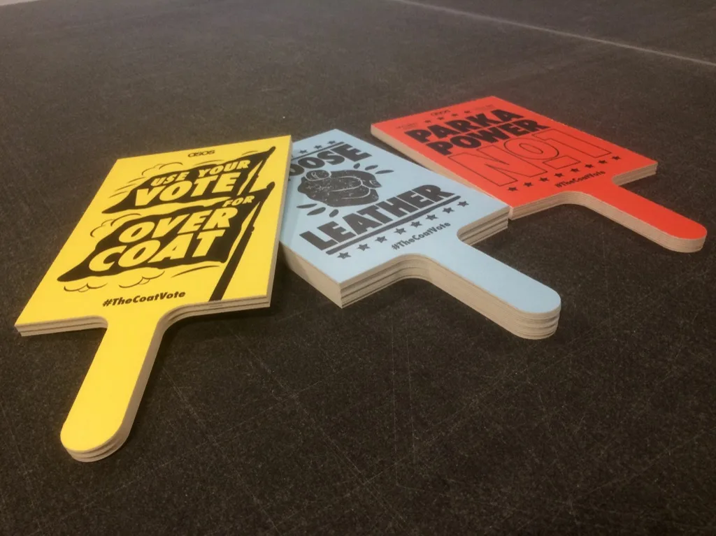
Relevant workshop, material and process photos showing the kind of cutting work we support.
Materials and production fit
The fastest quote is a clean file with known material and thickness. The safest quote is a reviewed job when finish, fit or production risk matters.
The final result depends on more than the drawing.
Metal laser, acrylic laser, router and knife workflows have different edge and fit behaviour.
Some tolerance-sensitive jobs should be checked before acceptance.
Capabilities at a glance
Tolerance guidance across laser cutting, CNC routing and digital knife workflows, with reviewed quoting for critical fit.
DXF, DWG or vector PDF files with real cut paths at the correct scale.
Fabricators, engineers, sign shops, OEM-style buyers, maintenance teams, shopfitters and installers.
Suitable for standard flat cutting files where fit is not critical or where the buyer has allowed clearance.
Best for tight fits, press fits, moving parts, samples, replacement parts, assemblies and finish-critical faces.
Sydney production support from Botany NSW, with pickup or delivery for suitable Australian jobs.
Instant pricing
Use instant pricing when standard cutting tolerance is acceptable and the file has sensible clearances.
Reviewed quote
Use reviewed quoting when fit, alignment, repeatability, face quality or assembly success is critical.
Cutting technologies
The best process is selected around material, thickness, finish, geometry and whether the file is ready for instant pricing.
Technical guidance
Tolerance should be discussed in context rather than promised generically across all materials, thicknesses and processes.
Tabs, holes and slots should allow realistic clearance for the process and material, especially where parts must assemble.
If a part is copied from an existing sample, measure the critical dimensions and send photos or a physical sample context for review.
If a tolerance issue would cause install failure, machine downtime or rejected batch work, reviewed quoting is the safer pathway.
Related services and materials
Use these pages to compare the relevant process, material, location or application details.
Common questions
Tolerance depends on material, thickness, geometry and process. Critical tolerance work should be reviewed before production.
Yes, holes and slots can be cut from suitable files, but very small or fit-critical features should be reviewed.
Press-fit or tight-fit parts should usually be reviewed because clearance and material behaviour matter.
Replacement parts can be reviewed from drawings, dimensions, photos or samples, but should not be treated as automatic instant-quote work.
Quote-ready files
Use instant pricing for clean cutting files, or send complex jobs through reviewed quoting when production decisions matter.