Pre-production packaging verification
Digitally cut, crease, perforate and kiss-cut packaging dielines so structure, folds, fit and artwork alignment can be reviewed before hard tooling or scheduled production.
Flat cutting and conversion only. Packaging design, product protection, compliance and final tooling approval remain with the customer or responsible packaging specialist.
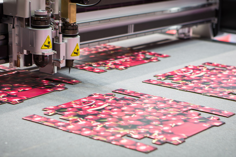
The existing Packaging & POS page covers the broader supply of flat packaging and display components. This guide addresses the narrower approval workflow: converting a controlled dieline into physical samples that can be folded, assembled, measured and reviewed.
Cut and creased cartonboard blanks for checking panels, closures, glue flaps, tuck features and the assembled pack.
Digitally converted corrugated boards for fitments, cases, dividers, presentation packs and structural packaging reviews.
Screenboard and display-board components used to assess tabs, slots, folds, product clearances and assembly order.
Chipboard and greyboard panels for covers, box components, inserts and wrapped structures where flat-part size and fit need checking.
Approved foam, card and board profiles for assessing product location, presentation and interaction with the outer packaging.
Cut-to-print work using supplied registration information so the physical result can be checked against artwork and finishing intent.
The digital knife table maps different line types to the appropriate cutting or forming tool. The file must distinguish every operation clearly.
Outer profiles, windows, apertures, tabs, slots and internal cut-outs are processed without a steel-rule die when the material and geometry suit digital cutting.
Fold-assist lines can be applied with pressure and tooling selected for the actual board. Grain direction, coating, print, laminate and board thickness can change fold behaviour.
Tear lines, opening features and removable sections can be mapped as perforation operations. The cut-to-gap pattern must be defined or approved before production.
Selected films and adhesive-backed materials can be reviewed for kiss-cutting where the face layer is cut while the liner remains substantially intact.
DXF or DWG is preferred for controlled cutting geometry. AI, EPS, SVG and correctly exported vector PDF files are also accepted for review.
A dieline cannot be assessed separately from the intended substrate. Crease response, slot fit, tearing and edge quality change with material construction.
The current LCE packaging pages publish common board examples and cutting envelopes. They are planning references, not automatic acceptance of every sheet.
The current SBS/FBB guide covers common examples from approximately 230–450 gsm, with heavier specialty grades reviewed separately.
The current guide shows indicative examples from approximately 600–2000 gsm depending on the required signage, display or packaging structure.
Single- and double-wall corrugated sheets are supported within the digital-knife material and geometry envelope.
Packaging and board pages publish beds up to 1500 × 3000 mm. The usable area is confirmed against material, machine, print-registration and handling requirements.
As an early digital-knife DFM guide, structural tabs and webs should generally not be finer than the material thickness. This is not a guaranteed minimum.
Board stiffness, flute direction, grain, coating, fold direction, unsupported length and tool access all matter. Critical tabs, slots and folds are reviewed from the actual file and substrate.
Treat each physical review as a controlled revision step. The approved dieline—not an unmarked sample—must remain the production reference.
Provide the product, substrate, pack objective, dieline, quantities, print state, required date and the decisions the physical set must support.
LCE checks scale, layers, duplicate paths, operations, material suitability, feature risks and the information needed to quote.
Parts are cut, creased, perforated or kiss-cut as quoted, then supplied flat unless assembly or other finishing is expressly included.
The customer checks product fit, fold behaviour, graphics, assembly, protection and every required compliance or commercial criterion.
Changes are returned as a new controlled file or clearly marked instruction. The next set must identify the new revision and superseded version.
The responsible party signs off the final dieline and material specification before digital production or transfer to a tooling supplier.
There is no universal sample quantity or economic crossover point. Quote the number of physical sets required for the actual approval process, then quote the intended production quantity separately.
Pricing is driven by material, sheet usage, cutting length, crease/perforation/kiss-cut operations, printed-sheet setup, nesting, quantity, packing and delivery. Repeated approved files and efficient multi-up layouts can reduce per-unit cost.
The published typical dispatch is 1–5 business days after artwork, material and quantities are confirmed. File repair, material sourcing, print production, approval cycles and revised sets add their own schedule; use the written quotation for the job-specific commitment.
Digital cutting works directly from the controlled file and can avoid commissioning a steel-rule die while geometry is still being reviewed. It also supports approved scheduled quantities when digital production is commercially suitable.
Hard tooling may be more suitable at a different production scale or for a converter’s established process. LCE can supply an approved digital dieline and physical parts, but the customer and tooling or packaging supplier decide when and how to transfer the design.
Do not assume identical crease, cut or assembly behaviour when moving between digital tools, a steel-rule die, another board batch or another production plant. Requalification belongs in the release plan.
Archive the released dieline, approval record, substrate specification and physical reference together. A reorder should identify the approved revision and any changed board, printer, coating, laminate or downstream process. If any of those inputs change, review whether a new physical approval set is required before the updated work is released.
A physical sample helps responsible teams inspect the pack, but it does not by itself prove transport performance, stacking strength, shelf life, barrier properties, tamper evidence, food contact, pharmaceutical suitability or legal compliance.
LCE converts the approved flat file in the nominated material. Packaging engineering, product protection, labelling, regulatory claims, material certification, transit testing, filling-line compatibility and final release remain with the customer or qualified packaging specialist.
Any printing, laminating, gluing, folding, assembly, testing or certification is included only when the written quotation says so. Otherwise parts are supplied flat for the customer’s controlled assessment and downstream process.
Send the controlled file, substrate specification, operation layers, required quantity and approval deadline for review.
Cutting Engineering & Fabrication in Sydney. Laser Cutting Experts Offers High-Precision Cutting Services for Engineering & Fabrication in Sydney Australia.